Joined: Dec 23, 2005 Posts: 4127 Location: Mount Hope, KS USA
Audio files: 97
Posted: Mon Aug 06, 2007 7:45 pm Post subject:
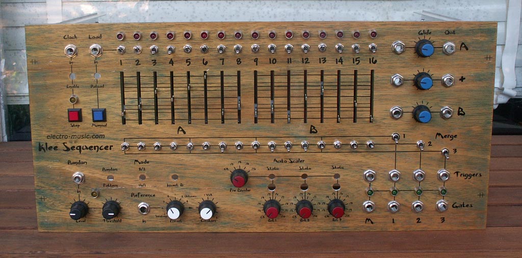
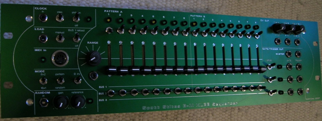
feat of Klee
After that, these two jokers pulled me in on their evil plan. "Scott, you handle this board while I do this one"....rrrriiiiigghhhhttttt. As things turned out, Andy did both boards, fortunately for all concerned.
My bit was getting the schematic files to the point where they could be used to design a PCB. Up until that point, I'd used Express Schematic as a free drawing tool, with no intention of ever designing a PCB. As print schematics, the original set is OK, but as a front end tool in making a PCB using the PCB program, they were a trainwreck. Express PCB would do nothing more than barf all over them.
So, the original schematics have been completely redrawn and divided between the Analogue Board functions, the Digital Board functions, and the Front Panel/Interconnect schematic. The ref designators were re-ordered to make sense and to point to which board they're from. Andy's Krunk-O-Matic connection system sprang from this redraw, so it added the sockets, etc., and made the entire design a much more build-friendly project. And, of course, I'm working on the documentation (ops, build, and calibration).
After that, we tapped Bill for the most painful and work intensive part of it - putting together a Kit, and to lend his expertise for proto-testing to make sure there are no hidden surprises. He's also been a big help in identifying the proper parts (which the protobuild will also serve to verify).
We've got one more very well-known gent on-board as the fourth protobuilder. I'll let him reveal who he is, if he chooses, but I'm excited about it.
Joined: Jun 30, 2005 Posts: 761 Location: Utrecht, NL
Posted: Wed Aug 08, 2007 6:12 am Post subject:
Is there a reason why the pots, switches and LEDs have been removed from the latest BOMs (or am I just looking the wrong place)? _________________ http://www.casia.org/modular/
Joined: Dec 23, 2005 Posts: 4127 Location: Mount Hope, KS USA
Audio files: 97
Posted: Wed Aug 08, 2007 6:43 am Post subject:
Of course! To test the coriolis effect, we should have just sent the boards straight to the coriolis
Etaoin, the BOMs Bill uploaded contain the parts for the boards and the bits for connecting the panel parts fo the boards (the housings and header pins, and so forth) should one go that route.
I'm pretty sure he's working up the panel parts BOM, too. I don't think there'll be a kit for that, because those parts may vary among builder's preferences for switches and stuff.
Joined: Jun 30, 2005 Posts: 761 Location: Utrecht, NL
Posted: Wed Aug 08, 2007 10:15 am Post subject:
Quote:
I'm pretty sure he's working up the panel parts BOM, too. I don't think there'll be a kit for that, because those parts may vary among builder's preferences for switches and stuff.
Indeed, but I just wanted to check the number of SPST and SPDT switches I needed and had to go back to an ealier BOM for that. No problem, as I assume these numbers haven't changed. _________________ http://www.casia.org/modular/
Joined: Dec 23, 2005 Posts: 4127 Location: Mount Hope, KS USA
Audio files: 97
Posted: Wed Aug 08, 2007 10:25 am Post subject:
Nothing has changed there. Bill's proven to be a great second pair of eyes, so if anything would change, it'd be the result of a mistake from moi. I don't see any mistakes, though - it checks out against my list of front panel elements.
Joined: Apr 17, 2006 Posts: 2812 Location: New York
Audio files: 25
Posted: Thu Mar 06, 2008 5:17 pm Post subject:
OK, here are the Klee Bills of material. Just add (1) 100K 1% resistor and (1) 1K resistor to the BOM. I forget which board that was for. The rest is accurate and should be fine .........
Joined: Apr 17, 2006 Posts: 2812 Location: New York
Audio files: 25
Posted: Sun Mar 09, 2008 7:28 am Post subject:
Here is an excerpt from Scott's fine Klee Build document. The tables contain all the parts, including the values and switch configurations, that you will need to build the Klee front panel assembly. When you get you boards, you will then be able to get you full documentation which includes operation, building, and schematics, assembly diagrams A very complete package I might add
As for the LED's, Scott uses LOW CURRENT type LED's. The forward current of 2 MA was chosen as to not over drive the shift register IC's he uses in the design.
Now that you have the BOM for the front panel, it will be up to you to choose or design a panel to your specifications. Based on this, you specify exact parts numbers for yourself since the forum factors of your parts will vary to someone else's. For example, larger pushbutton, sliders instead of pots, etc ......
Joined: Jan 13, 2008 Posts: 28 Location: Toronto, Canada
Posted: Sun Mar 09, 2008 11:51 am Post subject:
Bill, thanks for advice about 2mA leds.
But, can be that leds Uncle Kruncus installed draw only 2mA each? which parts is these, - and if not digikey who offers them?
Also, i believe Switches fonik used, do have pretty nice feeling touch, so i'd be interested using them as well... Would be more than glad if someone can point my nose to the source.
Both of Klees mentioned above do have very nice and clever panel design.
Viewing through digikey online catalog, i found these panel mount LEDs, which draw about 20mA each - therefore, i assume they are not applicable because of that..
Thanks in advance...
Kart
67-1147_50-ND.jpg
Description:
Filesize:
240.49 KB
Viewed:
526 Time(s)
This image has been reduced to fit the page. Click on it to enlarge.
609-2212-120,609-2212-130,609-2212-140[2].jpg
Description:
Filesize:
245.57 KB
Viewed:
547 Time(s)
This image has been reduced to fit the page. Click on it to enlarge.
Joined: Apr 17, 2006 Posts: 2812 Location: New York
Audio files: 25
Posted: Sun Mar 09, 2008 1:17 pm Post subject:
Here, shown below this message, are T-1 3/4 size LED's that are of the 2 MA low current type you need for hte Klee to work correctly. You can then use any LED holder that fits your fancy I use the Cliplite LED holders. They work well. The attached data sheet will show you all the details. Just make sure you choose a holder that they recommend for the T-1 3/4 LED size. Also, be aware of the panel thickness when ordering LED holders so that they will "snap" of mount correctly. My panel thickness is 3 MM and they fit like a glove ! Digikey and Mouser both carry these "Cliplite" holders for these LED's.
GREEN:
Digikey PN 516-1327-ND
Mouser PN 638-HLMP-4740
RED:
Digikey PN 516-1325-ND
Mouser PN 638-HLMP-4700
YELLOW:
Digikey PN 516-1326-ND
Mouser PN 638-HLMP-4719
Hope this information will help you in your quest for LIGHT !!
Joined: Apr 17, 2006 Posts: 2812 Location: New York
Audio files: 25
Posted: Sun Mar 09, 2008 1:22 pm Post subject:
Quote:
Also, i believe Switches fonik used, do have pretty nice feeling touch, so i'd be interested using them as well... Would be more than glad if someone can point my nose to the source.
Just give Fonik a shout ........ he is a real nice guy and does not bite either
Just another word on the LED's, whatever you do, don't use the 20MA low efficiency types with the 6.8K limiting resistors called out (you will see this on the schematic when you get it) , you may not get uniform brightness.
Joined: Apr 17, 2006 Posts: 2812 Location: New York
Audio files: 25
Posted: Sun Mar 09, 2008 1:54 pm Post subject:
Quote:
Bill, With the 2ma LED's you specified, you are not using any current limiting resistors?
Yes, as with any LED, you should use a limiting resistor. The forward voltage for this LED operating @ 2MA is 1.8V. Scott uses the CD4034 to drive the LED's and that IC puts out about 15V when using a 15V supply. He uses a limiting resistor of 6.8K. So, caluclating that LED current becomes easy: Vresistor=15-1.8=13.2
13.2V/6800 Ohms =1.94 milliamperes ........ just about right my man
Joined: Sep 25, 2005 Posts: 1351 Location: Telford, PA USA
Posted: Sun Mar 09, 2008 2:04 pm Post subject:
Thank you for clarifying that. I was, for some odd reason thinking you had found a new kind of LED with built in limiters or something. I must have had my head in another place.
The LEDs I used are in fact the "20mA" ones, or something very similar. I didn't even look for low current types, 'cos I knew I'd have hassles trying to find them.
I found I could get those LEDs (they come fixed in that chrome holder, although you can punch them out and replace with other 5mm colours if you like) from Dick Smith for about $1 each. I bought 40 or so and then started testing.
Using a 15V supply and an array of 6K8 limiting resistors I found that with only 2mA going through them the brightness of the red ones was just fine. I hooked up 6 at a time and weeded out the 3 or 4 out of 40 which had an odd colour/brightness.
Scott actually used "standard" LEDs on his breadboard while testing the Klee. (a process which took a year or so) The main thing is to keep the limiting resistors at 6K8. This ensures that you won't cook your 4034s. These pattern LEDs really don't need to be very bright anyway, as there are often lots of them "on" and you only need to see whether they are on or off. They don't need to light up your studio/stage.
The 6 other LEDs are all driven by a 2N3904, and I found that the green version of that chrome bezel LED was quite dim with the 6K8 collector resistor. In this case you can drop the limiting resistor (as I did, to 4K7) as you're not stressing any chips in doing so. _________________ What makes a space ours, is what we put there, and what we do there.
Joined: Apr 17, 2006 Posts: 2812 Location: New York
Audio files: 25
Posted: Sun Mar 09, 2008 3:47 pm Post subject:
Quote:
Using a 15V supply and an array of 6K8 limiting resistors I found that with only 2mA going through them the brightness of the red ones was just fine. I hooked up 6 at a time and weeded out the 3 or 4 out of 40 which had an odd colour/brightness.
There's a good testimonial right there. Seems like if you have a bin full of LED's, give them try but first cull them out. The majority may work just fine it seems. But leave in those 6.8K's
Joined: Dec 23, 2005 Posts: 4127 Location: Mount Hope, KS USA
Audio files: 97
Posted: Sun Mar 09, 2008 6:30 pm Post subject:
Uncle K and State Machine got it right - specifying 2 mA LEDs was a means to ensure people got consistent results. On the breadboard, I used regular old red LEDs - they were in a bag I got from somewhere, sometime. I was surprised at the brightness I got using 6K8 resistors, 6K8 being a much higher value than one normally associates with LED current limiting resistors. I was suspicious that perhaps other people would get LEDs that didn't perform as well, so the solution was to specify an LED I knew would work. I never tried green LEDs, BTW, if memory serves me.
Anyway, once I got the 2 mA LEDs to install in my Klee, I really couldn't see much of a difference, if any. Let me tell you, the brightness on the LEDs is just fine - they are no more bright or any less bright than the LEDs on my other equipment. I love watching that Klee run - you can just see the musical patterns it's batting around with the pattern and gate bus LEDs. Also, it's a real kick to turn out the lights and just watch the thing interact with everything else.
Here are a couple of pics of the Klee, integrated with some of my other stuff "Lights on" really was taken with a flash (it was daytime when I took the pic yesterday). "Lights off" is with no flash. You can see that the Klee LEDs are just the same brightness as the LEDs on the FX and synths. For the trivia lovers out there, to the right and in the background is the original Klee breadboard.
And, what the heck - here's a sample of what the pictured pic sounds like (after all, I'm logged in at a blazing 37333 bps). In this sample, the Klee is controlling the DSC2000 for the percussive sound, and it's also controlling the Dim C - take a look, you can see the Klee is patched into the Dim C control input. I have the Klee set so it rocks the voltage up and down sharply, and you can hear the rhythmic effect in the sample, synced to the percussive DSC2000. Recorded "live" (no multi-tracking or over-dubbing). God I love my Klee and Dim C.......
Cheerio,
Scott
klee_dim_space.mp3
Description:
The sound of the patch in them there pictures...............
Filesize:
5.9 MB
Duration:
3:13
Viewed:
2086 Time(s)
lights_on.JPG
Description:
KS Studios, Lights On
Filesize:
402.19 KB
Viewed:
508 Time(s)
This image has been reduced to fit the page. Click on it to enlarge.
lights_off.JPG
Description:
KS Studios, Lights Off
Filesize:
222.69 KB
Viewed:
514 Time(s)
This image has been reduced to fit the page. Click on it to enlarge.
You cannot post new topics in this forum You cannot reply to topics in this forum You cannot edit your posts in this forum You cannot delete your posts in this forum You cannot vote in polls in this forum You cannot attach files in this forum You can download files in this forum


 Forum index » DIY Hardware and Software » Klee sequencer


 FAQ
 Calendar
 Search
 Memberlist
 Usergroups
 Register
 Profile
 Log in to check your private messages
 Log in
 Chat Room


 , I just had to dig out


 A very complete package I might add