Joined: Jan 14, 2010 Posts: 6058 Location: Moon Base
Audio files: 728
Posted: Sun Sep 07, 2014 8:59 pm Post subject:
Melody Generator XL Subject description: more bits and a chromatic version
While I was experimenting with the melody generator I started thinking, why not make it larger with a 16 step counter instead of 10 ?!
The first version I drew up [1.0] uses a CD4029 (binary counter) + CD4514 (4-TO-16 decoder) to create a 16 step counter,
replacing the CD4017 in the orginal melody generator, followed by a CD4067 (16 channel mux) replacing the CD4051.
I don't have a CD4514, so the next version [1.1] uses another CD4067 as a decoder instead.
Although I have a couple of those CD4067's I rather use them for something else instead. So the next version [2.1]
uses 4x CD4051 (got a bunch of those) to replace the CD4067's.
note, these are all untested.
Melody Generator XL - V1.0.gif
Description:
Melody Generator XL - V1.0
Filesize:
63.4 KB
Viewed:
2253 Time(s)
This image has been reduced to fit the page. Click on it to enlarge.
Melody Generator XL - V1.1.gif
Description:
Melody Generator XL - V1.1
Filesize:
64.14 KB
Viewed:
1435 Time(s)
This image has been reduced to fit the page. Click on it to enlarge.
Melody Generator XL - V2.1.gif
Description:
Melody Generator XL - V2.1
Filesize:
88.4 KB
Viewed:
1590 Time(s)
This image has been reduced to fit the page. Click on it to enlarge.
Joined: Jan 14, 2010 Posts: 6058 Location: Moon Base
Audio files: 728
Posted: Sun Sep 07, 2014 9:02 pm Post subject:
While looking at the schematics it seemed kinda ridiculous to have 2 4-bit binary to decimal converters in there.
And thinking a bit more about it I realized that I only have to compare the 4 bits and if they are the same reset the counter.
Well, I recently done something similar creating a 4029 preset counter with bounce.
So I tested it [V3.0] and it works . however there are 2 problems with doing it binary instead of decimal.
As you can see in the previous circuits the in-/outputs of the converters aren't lined up but shifted one step
(2 steps in the original design). If you don't do this the counter won't count when the CTRL inputs are 0000 & 0001
and furthermore it can only count 15 steps max instead of 16.
Adding a step in binary is a bit more complex. It could be done with a full adder which seems to exist as a CD4008,.. if you can find it.
I did however make it possible to get 16 steps by adding the E input, when low the CD4029 doesn't get reset and counts from 0 to 15
Then there is another problem; threre is no step 0 to use as the output. I solved this by detecting when all outputs are low,
using a 4-input OR gate (diodes + resistor) followed by a transistor inverter.
But I didn't really like the transistor on the output in [V3.0] so I drew a version [V3.1] which uses a CD40106 inverter instead,
And I also used one to invert the E input which makes more sense to me. Which leaves 4 gates unused,..
If you don't have the CD4077 (quad XNOR) but do have the CD4070 (XOR) you could use it together with those inverters [V3.2].
Or make 4 oscillators and attach them to the CTRL inputs
Melody Generator XL - V3.0.gif
Description:
Melody Generator XL - V3.0
Filesize:
61.59 KB
Viewed:
1312 Time(s)
This image has been reduced to fit the page. Click on it to enlarge.
Melody Generator XL - V3.1.gif
Description:
Melody Generator XL - V3.1
Filesize:
67.09 KB
Viewed:
1212 Time(s)
This image has been reduced to fit the page. Click on it to enlarge.
Melody Generator XL - V3.2.gif
Description:
Melody Generator XL - V3.2
Filesize:
66.01 KB
Viewed:
1287 Time(s)
This image has been reduced to fit the page. Click on it to enlarge.
Cool circuit PHOBoS. Took me a while to understand how it divides by 1, but I think I got it. With each clock it counts to 1 and immediately resets, producing a brief low pulse at the output.
However, thinking about a melody generator built with this, one thought struck me. The circuit will generate 16 frequencies, with a ratio of 1:16 between the lowest and the highest tone. That's 15 octaves apart...
It would be nice to have a circuit that uses 16 different dividers, but in a way so that the maximum ratio between lowest and highest frequency is something between 1:2 and 1:4. For example, if it would divide by 16,17,18,...31.
I tried to come up with a circuit for that and the closest I found is below. It uses Johnson counters and divides in 15 steps between 10 and 40. Too bad that the dividers are not sorted and that the division by 24 appears twice, haven't found an easy way around that yet.
divider10to40.PNG
Description:
Filesize:
28.11 KB
Viewed:
1186 Time(s)
This image has been reduced to fit the page. Click on it to enlarge.
Right after posting this it struck me that it could be done exactly like PHOBoS did, but with a longer counter. One could use a 4040 for example and a magnitude comparator. My circuit library doesn't have the 4063 or 4585, so I used the 74LS85. This circuit should divide by 16,17,18,...31 if I got it right. Drawback is, however, that the resulting note frequencies wouldn't match the tones in a Just Scale too well.
Divider16to31.PNG
Description:
Filesize:
23.08 KB
Viewed:
978 Time(s)
This image has been reduced to fit the page. Click on it to enlarge.
Found a better CMOS library for Kicad meanwhile. Maybe it could even be done like this, but the resulting output pulses from the comparator would always be really short.
Nevertheless, I would expect that the Johnson counter version sounds better because of the dividers it uses.
Divider16to31V2.PNG
Description:
Filesize:
17.54 KB
Viewed:
1077 Time(s)
This image has been reduced to fit the page. Click on it to enlarge.
Joined: Jan 14, 2010 Posts: 6058 Location: Moon Base
Audio files: 728
Posted: Tue Sep 09, 2014 1:50 pm Post subject:
synaesthesia wrote:
The circuit will generate 16 frequencies, with a ratio of 1:16 between the lowest and the highest tone. That's 15 octaves apart...
It divides by 2,3,4,5,6,7,8,9,10,11,12,13,14,15,16.
/2 = 1 octave, /4 = 2 octaves, /8 = 3 octaves and /16 = 4 octaves (max)
But the pulsewidth stays the same (1 CLK cycle) so it's not a 50/50 output (except for the /2). (see diagram)
The last version you drew [Divider16to31V2] is pretty similar to the one I made. I wasn't familiar with the 4063/4585 so I used the XNOR's,
but that makes it even easier. I don't see a need for using the Q4 output though.
Quote:
Took me a while to understand how it divides by 1, but I think I got it. With each clock it counts to 1 and immediately resets, producing a brief low pulse at the output.
Actually the /1 isn't possible with my circuit because I don't use the reset pulse which as you already mentioned would be very short.
I think you could add a S/R flip flop to it so it's the same length as the CLK input, but that's more chips which I tried to keep at a minimum.
What I did is use the first step, when all outputs are 0, as the output. just as in the original melody generator.
I also thought about using the 4040, but it has that inverted CLK input so I used the CD4029 instead.
However you could use the 4040 with more comparators for an XXL version (go crazy and chain a couple of 4040's )
You could also use a 4040 in the original circuit instead of the 4017. That would give you different octaves out at audio
frequencies, which isn't too interesting, but with an LFO it's nice as a CLK source for a sequencer/rhythm generator.
Melody Generator XL - V3 timing.gif
Description:
Meoldy Generator XL V3 timing diagram
Filesize:
36.38 KB
Viewed:
1062 Time(s)
This image has been reduced to fit the page. Click on it to enlarge.
You are correct about the octaves of course. My bad math.
With regard to the /1 operation, you are using PRESET ENABLE with J1 to J4 wired to 0V. Wouldn't that have the same effect as an asynchronous reset?
Joined: Jan 14, 2010 Posts: 6058 Location: Moon Base
Audio files: 728
Posted: Tue Sep 09, 2014 3:02 pm Post subject:
synaesthesia wrote:
With regard to the /1 operation, you are using PRESET ENABLE with J1 to J4 wired to 0V. Wouldn't that have the same effect as an asynchronous reset?
yes it does, and you just made me realize something (maybe that's what you're getting at)
Quote:
As you can see in the previous circuits the in-/outputs of the converters aren't lined up but shifted one step
(2 steps in the original design). If you don't do this the counter won't count when the CTRL inputs are 0000 & 0001
and furthermore it can only count 15 steps max instead of 16.
Adding a step in binary is a bit more complex. It could be done with a full adder which seems to exist as a CD4008,.. if you can find it.
There is no need to shift all the 4 bits with an adder, just delay the comparator output with 1 CLK cycle.
does that happen when using a 4040 ? I'll have to experiment a bit more with it,.. _________________ "My perf, it's full of holes!" SoundCloudBandCampMixCloudTwitchYouTube The Golden Shrimp Guild
Joined: Jan 14, 2010 Posts: 6058 Location: Moon Base
Audio files: 728
Posted: Sun Sep 14, 2014 6:18 pm Post subject:
Chromatic Melody generator Subject description: 12 notes, 8 octaves
I designed a chromatic version with 12 notes and 8 octaves
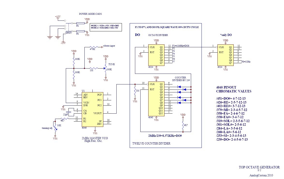
It's basically a combination of the standard melody generator and the Top Octave Generator by Analog Custom*
*which was posted here by RichardC64, but probably originated from this TOG thread
The original melody generator works by using a mux [CD4051] to reset a counter [CD4017] to create different divisions
of the original frequency, resulting in different notes. The TOG also works by resetting a counter [CD4040] (when all the
outputs that have diodes connected to them are high) except it doesn't have a mux but uses a seperate counter for
each note (it's polyphonic). So to create the chromatic melody generator I only used 1 counter, with a diodematrix to
create the 12 divisions and a mux [CD4067] to select which one to use.
I first translated the 4040 pinout chromatic values to the Q outputs (2..9) which resulted in the following table:
Code:
| C# D D# E F F# G G# A A# B C
----------------------------------------
Q2 | x x x x x x x x
Q3 | x x x x x x x
Q4 | x x x x x x x x
Q5 | x x x x x x
Q6 | x x x x x x x
Q7 | x x x x x x
Q8 | x x x x x
Q9 | x x x x x x x x x x
----------------------------------------
I then spend about 2 days trying to figure out if it was possible to reduce the amount of diodes by combining some
of the AND functions (the diodes and pullup resistor make up a multi input AND gate) by using actual AND gates.
I did get it reduced to about 50% using 8 AND gates instead, but it's easier (and probably even cheaper) to just
use diodes and solder it on some stripboard.
The last 3 outputs of the mux [I/O13...I/O15] don't have anything connected to them, so when selected there
won't be any sound. The 'C' is connected to both I/O0 and I/O12 but when I/O0 is selected it will be 1 octave
lower, more on that later
The reset pulse needs to be divided by 2 to make a 50/50 squarewave which in the TOG is done by another
counter [CD4024], this also provides the different octaves. I used a CD4040 instead and added a mux to
select beween 8 octaves.
As mentioned when I/O0 of the CD4067 is selected the 'C' note will be one octave lower. This way the keyboard
starts with a C instead of C#. In the TOG this is achieved by using one more counter [CD4024] to create the extra C.
But since the melody generator isn't polyphonic I needed a counter and some sort of switch to select it when that C
is selected. I could add another mux but that seemed a bit overkill so I looked for a way to do it with one chip.
I first puzzled around for a while using a CD4013 which contains 2 D-type flipflops with S/R inputs. One to divide by 2
and then the other to switch,.. except I didn't get that part work.
So I thought about what other counters/dividers I had,.. 4017 ? hmm,.., 4029 with it's jam inputs ? hmmmmm,..
Well that actually worked . Used as a counter the Q1 output is one octave lower then the input frequency. And by
connecting the input to the corresponding jam input (J1) aswell the output will be that same frequency when the preset pin
is high. It only needs to divide for that lower C which is when the ABCD note select inputs are all low. So by using an
OR gate the preset pin will be high when the ABCD inputs aren't all low.
I haven't tested it yet, except for the CD4029 octave switch and that seems to work, I just don't have enough
diodes left (there are 57 in the matrix). Well actually I do have ±500 1N4007's but they are too large to fit
next to each other and besides that I don't have any stripboard which will make it easier to put together.
But diodes and stripboard are ordered
edit: fixed link for TOG thread
Chromatic Melody Generator.gif
Description:
Chromatic Melody Generator circuit diagram
Filesize:
94.59 KB
Viewed:
1542 Time(s)
This image has been reduced to fit the page. Click on it to enlarge.
Joined: Jan 14, 2010 Posts: 6058 Location: Moon Base
Audio files: 728
Posted: Wed Sep 17, 2014 9:37 am Post subject:
so do I
I'm first testing a smaller version, which I'll post more info on later, but I ran into a weird problem.
It needs a divider on the output to turn the reset pulse into a squarewave and create the octaves.
On the small version I'm testing I used a CD4520 to which I could add resistors like the Gong Drone has .
I build it straight onto some perf without breadboarding it first but it doesn't work.
I thought it might be a bad chip, bad solder connection or short, or something else like that.
However I'm testing it on breadboard and apparently using the CD4520 just doesn't work,
if I replace it with a CD4040 or CD4029 it works fine.
(so now I have some resoldering to do) _________________ "My perf, it's full of holes!" SoundCloudBandCampMixCloudTwitchYouTube The Golden Shrimp Guild
Strange. As you pointed out, one difference is that the 4040 counts on the negative edge, and the 4520 counts on the positive edge. The other difference is that the 4520 is a synchronous counter, while the 4040 is a ripple counter. Maybe that makes a difference here.
Joined: Jan 14, 2010 Posts: 6058 Location: Moon Base
Audio files: 728
Posted: Wed Sep 17, 2014 2:33 pm Post subject:
synaesthesia wrote:
one difference is that the 4040 counts on the negative edge, and the 4520 counts on the positive edge.
That's why I also tested with a CD4029 although I don't think that would really matter. But I was just looking
at the datasheet and the 4520 can be both positive and negative edge triggered, depending on using the Clk or Enable input.
So I tried both but it doesn't work. I also tested putting an inverter in series (CD40106 & CD4069) but then even the
CD4040 doesn't work. Haven't tested with a CD4049 yet. _________________ "My perf, it's full of holes!" SoundCloudBandCampMixCloudTwitchYouTube The Golden Shrimp Guild
Joined: Jan 14, 2010 Posts: 6058 Location: Moon Base
Audio files: 728
Posted: Thu Sep 18, 2014 1:19 pm Post subject:
PHOBoS wrote:
Haven't tested with a CD4049 yet.
I did and that works, but I'm using a CD4040 now anyway.
So the mini version,.. which actually somewhat inspired by the Gong Drone
I thought it might be nice to use notes from a chord, which it will step through like a little arpeggiator.
I first wanted to do 4 notes for a major 7 chord,. but since a minor chord is only one different note, and I'm using an 8 input mux
I decided to add that aswell. So ABC = xx0 plays the major7 notes and xx1 plays the minor7.
Next I made a list of all the chords and which diode connections I would need for the different notes.
And from this list I choose the one with the least amount of diodes which turned out to be F#.
I put it together and after having replaced the CD4520 with a 4040 it worked, however it sounded a bit off.
So I checked if I had the correct notes and corresponding diode connections which all seemed to be OK.
But I then recalculated the divisions, comparing them with the numbers from the TOG and noticed something.
The list of divisions and corresponding diode connections of the TOG isn't complete; Q1 is missing
(without it you can't get any odd divisions) so here is the updated list:
Code:
| C C# D D# E F F# G G# A A# B C
------------------------------------------
Q1 | x x x x x x
Q2 | x x x x x x x x x
Q3 | x x x x x x x x
Q4 | x x x x x x x x x
Q5 | x x x x x x x
Q6 | x x x x x x x
Q7 | x x x x x x x
Q8 | x x x x x x
Q9 | x x x x x x x x x x x
------------------------------------------
After I'd added the diodes it sounds a lot better, so I'm glad I tested this first before trying the large one.
Speaking of which I think you can just make the lower C by /478 instead of doing the octave down shift
with the CD4029 afterwards. (added those connections too)
some more info about the schematic
All the notes needed a connection to Q9 of U1, so I only used 1 diode and connected it straight to the reset input.
The connection bewteen Q9 and the reset input of U2 is just for easy soldering.
I should probably record something although it's not that interesting right now,.
miniARP.gif
Description:
Filesize:
66.49 KB
Viewed:
1221 Time(s)
This image has been reduced to fit the page. Click on it to enlarge.
Joined: Jan 14, 2010 Posts: 6058 Location: Moon Base
Audio files: 728
Posted: Mon Sep 22, 2014 5:07 pm Post subject:
I build the Chromatic Melody Generator.
I started with soldering just the 4040 and diodematrix so I could test if the notes sounded correct.
Well they didn't. Some seemed ok,. but a couple were way off (like an octave higher). So I added another CD4040
(on breadboard) in parallel with the CLK and Reset lines and connected some LED's on the outputs so I could see how far
it counted. They were all wrong so I did some measurements and found a short between two tracks. I couldn't really see
anything but after some cleaning with a brush most of the notes were ok. However there were still 2 notes off and the weird
thing was that there was a reset pulse at the right time but the counter didn't reset, instead it skipped a couple of steps.
I coudn't really find anymore shorts and I wondered if having the other CD4040 connected might have omething to
do with it. So I disconnected it and that worked.
The next thing I added was an oscillator. I used a CD4046 in the same way as in the TOG schematic, but left
the tuning adjust trimpot and vibrato out. And then carried on soldering the rest of the circuit before testing it.
On the first test I didn't get any sound out. The oscillator was working, the divider was counting but something wasn't
working correct. I took the CD4067 out and tried making connections manually to select the different notes.
And after swapping out some CD4040's I got that part functioning correct too. In the meantime I had added a larger
timing capacitor to the oscillator so I could listen to all the outputs of the CD4040 that produces the notes, but when I
removed that some notes didn't work anymore. It did when I lowered the supply voltage. And after spending some
time trying to figuring out what might be the problem I got the idea of reducing the value of the pullup resistor
on the reset line. I was using 10K and it is 4k7 in the TOG. but I replaced it with a 2K2 just to be sure
And that did it!
That was probably the reason why I had to swap some of the 4040's, they did seem to count correct when
tested on breadboard but didn't work in the circuit. And it might also be the same problem I had with the CD4520's
So I have to do some more tests with that one.
The Lower C works correct so no need for an extra divider. The only thing that is bugging me a little bit now is that
there is no sound when I/O13, I/O14 or I/O15 of the CD4067 is selected. Not that silence is bad but because it's all
grouped at the end it's very noticable when the D note select input is high. So now I'm thinking of reordering the notes
and leave I/O7, I/O11 and I/O15 unconnected. I'm also thinking of adding switches for each note so 'wrong' notes
can be turned off.
Below is a short range demo using a binary counter to increase both notes and octaves.
it's has a very wide range
PHOBoS - Chromatic Melody Generator - range demo.mp3
Joined: Jan 14, 2010 Posts: 6058 Location: Moon Base
Audio files: 728
Posted: Mon Sep 22, 2014 5:20 pm Post subject:
and here's the updated schematic.
note there is an error in the schematic, there shouldn't be a connection between pin 11 of U1 and pin 8 of U5.
pin 8 (and everything to the left of it) should of course be connected to GND. (updated schematic on page 2 of this thread)
Chromatic Melody Generator V2.gif
Description:
Chromatic Melody Generator v2
Filesize:
100.67 KB
Viewed:
1250 Time(s)
This image has been reduced to fit the page. Click on it to enlarge.
Joined: Jan 14, 2010 Posts: 6058 Location: Moon Base
Audio files: 728
Posted: Tue Sep 23, 2014 2:45 pm Post subject:
Here's the stripboard layout for the tone generating section. The rest is mostly point to point wiring so not much use in drawing that.
You could also just add a divider and some switches to make a simple keyboard.
I don't know why it only lists the first 7 diodes, but the rest are 1N4148 aswell, not that it matters much what you use.
Chromatic Melody Generator stripboard.jpg
Description:
Filesize:
809.89 KB
Viewed:
1085 Time(s)
This image has been reduced to fit the page. Click on it to enlarge.
|-------------------------+-------------|
| Chord | notes |
|-------------------------+-------------+
| Diminished triad | C D# F# |
| Minor triad | C D# G |
| Major triad | C E G |
| Augmented triad | C E G# |
|-------------------------+-------------|
| Diminished seventh | C D# F# A |
| Half-diminished seventh | C D# F# A# |
| Minor seventh | C D# G A# |
| Minor major seventh | C D# G B |
| Dominant seventh | C E G A# |
| Major seventh | C E G B |
| Augmented seventh | C E G# A# |
| Augmented major seventh | C E G# B |
|-------------------------+-------------|
I then converted them to get the divisions needed when using a counter to produce the right notes.
this resulted in the following list for the triads:
the one that immediately stood out for me is the minor triad that can be made by dividing a frequency by 4, 5 and 6.
Which is part of what the original melody generator does.
the major triad is also interesting with only 4 bits but I'll come back to that one with the seventh list.
The notes of both Major and Minor triads can be made with 5 bits
Code:
|------------------------|
| Major + Minor Triads: |
|------------------------|
| C 1/1 = 30 /30 11110 |
| D# 6/5 = 30 /25 11001 |
| E 5/4 = 30 /24 11000 |
| G 3/2 = 30 /20 10100 |
|------------------------|
Joined: Feb 18, 2013 Posts: 150 Location: south Germaica (schwabilon)
Posted: Sat Sep 27, 2014 7:26 am Post subject:
OH SHIT -
now you got my attention....
i was trying to build a "Three-toed sloth"-mashine with 4 chords. But i give it up the tuning is hard. (4cords [C,F,G,Dm] == 9 notes, -> 10 Trimpots, 3*4093) and i killed the old guitartuner while i had it on breadboard, seems he dont like the 5V Square....
a cool option for the (nonchords) melodygenerator will be a pentatonic switch (only C D E G A)....
You cannot post new topics in this forum You cannot reply to topics in this forum You cannot edit your posts in this forum You cannot delete your posts in this forum You cannot vote in polls in this forum You cannot attach files in this forum You can download files in this forum


 Forum index » DIY Hardware and Software » Lunettas - circuits inspired by Stanley Lunetta


 FAQ
 Calendar
 Search
 Memberlist
 Usergroups
 Register
 Profile
 Log in to check your private messages
 Log in
 Chat Room


 . however there are 2 problems with doing it binary instead of decimal.


 )



 (there are 57 in the matrix). Well actually I do have ±500 1N4007's but they are too large to fit


