for the pots attached to pins 6,9 & 13 anti-log would be perfect. I think that linear would be more suitable for the other 2,
but I haven't tested it.
Ha! Actually i guessed at first that log would be the best since these pots looked like frequency control somehow. It was not. i suppose i'm going to wire them to be used backwards (and yes lin is fine for the others).
Which brings me to a question: could someone explain just what's going on in this circuit? The part with two diodes in the initial stages looked to me like a sort of waveshaper (met in some LFOs), which it's obviously not ; like i said, i thought the other side seemed to form a simple oscillator à la 40106, there again i'm not sure at all! And the whole thing gets NANDed and then NANDed again with a non-oscillator…Wowowoh, i'd like to understand a bit of it! Not owning an oscilloscope, i can just try to figure out what's going on from what i hear, which doesn't bring me very far i must say.
Thanks in advance! _________________ ::U::N::S::C::H::N::E::L::L::
Joined: Jan 14, 2010 Posts: 6067 Location: Moon Base
Audio files: 730
Posted: Wed Apr 15, 2015 7:37 am Post subject:
piedwagtail wrote:
It's like a bar room brawl.
Easy to see the overall action but hard to predict where the next punch will be thrown
That's a good one!
The bits around U1c/U1d are actually 2 things mashed together. They have a standard (schmitt trigger) oscillator with
a variable frequency and the part with the diodes is also an oscillator but with a fixed frequency and a variable pulsewidth.
Both of those only work if the other input pin of the NAND gate is high but since they are attached to same output
and are both oscillators the whole thing becomes somewhat unpredictable. not that it is really chaotic but both
oscillators influence eachother.
NAND U1a just mixes the signals together and the output is only low when both inputs are high.
NAND U1b is a gated oscillator which only oscillates if the input attached to U1a is high.
NANDulator Anatomy.gif
Description:
Filesize:
26.35 KB
Viewed:
852 Time(s)
This image has been reduced to fit the page. Click on it to enlarge.
Joined: Jan 14, 2010 Posts: 6067 Location: Moon Base
Audio files: 730
Posted: Wed Apr 15, 2015 7:45 am Post subject:
So that got me thinking, instead of combining an oscillator with variable frequency and an oscillator
with variable pulsewidth, combine 2 oscillators that have both variable frequency and pulsewidth.
I haven't tested it so I don't know if it works (it should do something) or what useful capacitor values
are. but here's the schematic for:
The NANDulator V2 now with even more NANDulation!
sorry Robert
NANDulator V2.gif
Description:
NANDulator V2 (untested)
Filesize:
23.19 KB
Viewed:
1108 Time(s)
This image has been reduced to fit the page. Click on it to enlarge.
Thank you very much PHOBoS for your clear explanations about how the NANDulator NANDulates. So my guess was not that far off concerning the sub-circuits but i completely missed the proeminence of the chaos factor. What's weird is that the "PW control" mostly dictates frequency while the frequency control affects timbre for the most part. Strange… NANDul, so to say. And the last oscillator sometimes sounds a tad like a filter. i definitely was able at some point to hear harmonics while turning that pot!
Talking 'bout pots, thanks piedwagtail for the input, i'll stay with my backward logs tho!
And yeah, that V.2! Want to hear that!
Concerning V.1, i thought improving the layout with: bigger wire pads, putting the pads for the first pot in the correct order, adding an LED, a protection diode (think standalone noisebox). Makes sense? Or not. Stay tüned. _________________ ::U::N::S::C::H::N::E::L::L::
1. NANDulator core should work off 5V-15V
2. Have a pots only manual version that works from core headers
3. have diode inputs in and out possibly with switch
4. have a n number input CV and manual version
5. linear oscillator pitch if possible
6. CV should use vactrol/Silonex/homebrew control
7. CV should be +/-5V
8. CV board will require bipolar supply
9. outputs could be for main and monitor (and carry?); main could be CV'd
For a playable audio rate NANDulator the ideal set-up would be to inject some CVs and then manually interact with them.
For a gate rate NANDulator manual control sets the initial condition/offset - you allow the CV's to fight it out whilst you watch from the bar.
Theoretically
God only knows what NANDulators NANDulating NANDulators requires...
next
manual version with direct pots
Manual and CV version with opamp mixers driving optos
1 core and 2 control board options; one manual; one manual/CV
field report
OK, I've been watching a line on the 'scope going up and down in time with a +/-5V triangle wave
(I'm a little seasick)
Measuring voltages/currents/resistances and observing how little real information there is about opto resistive setups.
I wondered whether the typical filter sweep fun is simple for the ear and any old hack with a changing voltage works kind of....
( a lot of writing seems to be proof of engineering rather than consistent musical device).
I abandoned ideas and then had them rejoin the fight.
Driving a led with an almost reverse log response seemed possible but when I actually came to swap them out for 'real' optocouplers the cadmium reaction resistance was another matter. Silonex optos are virtually just switches; makes me wonder what people who use them are really achieving. Optos with transistors and opamp feedback loops were very narrow and difficult to use...perhaps I needed to expand my knowledge with some sort of bridge.
Conclusions:
1. If anyone needs 0-5V CV they can do level matching themselves. +/-5V will handle carry NANDulator inputs fine with a diode.
2. Silonex is not an option, the classic VTL5C3/2 I have gave 100M+ to 3k in parallel connection of the two sides. Problem for everyone will be the price of so many vactrols. I do have some opto-resistors so my next task is to try them with leds.
3. I'll use an inverting opamp to mix the CV and the manual Intial setting. The second opamp will conveniently invert and cut down the voltage swing for the led current control element.(more on the last part of that sentence later if it still works with the homebrew optocouplers)
next
Achieving 3k -40k with one premade homebrew opto and 2k-90k with another with better black heatshrinking.
What are the expected ranges that people get with homebrew optocouplers?
Best news the response is definitely reverse log not linear, this should get a better linear pitch response with the oscillators
I'm not as excited as I was when I realized how this could be done but I think I can move on from this research.
Optocoupling will always involve finetuning by the constructor, this isn't a particularly consistent pursuit.
Joined: Jan 14, 2010 Posts: 6067 Location: Moon Base
Audio files: 730
Posted: Tue Apr 21, 2015 7:57 am Post subject:
looks good umschmitt!
with that layout you could solder a header onto it that you can plug it into a breadboard to do some more experiments.
Robert, a while back I desined a circuit to convert a CV to resistance with a homemade vactrol. I'll see if I can find it
maybe you can get some ideas from that. For a PCB you could add extra solderpads for any NAND output to link them
or maybe hook up some LED's (I should try my 5x5 mini scope with it). A more universal version could be a board that
has an option to choose what you want to make and in what order you connect it. So it would have all the necessary
holes and traces to make 4 of those NANDulator cells (V1 with frequency and PWM control). but you could also make 4
standard oscillators or the original NANDulator and than connect in & outputs as you want (could make it patchable).
Of course this would require a larger PCB. Maybe add an extra space for 4 diodes or resistors connected to the output
to mix signals together.
I did a test with the 4 pot version of V2. I only have enough pots to test with 1 NAND gate though but it does work.
However it's also harder to control because you have to turn 2 pots at once if you only want to change frequency
or pulsewidth. I am thinking of doing a test with a bunch of LDR's instead of pots just to see how crazy that gets.
It will most likely be very hard to control. Maybe I'll add a solarpanel for power and let the sun have some fun with it
2 board solution.
NANDulator LDR v.1
Panel board 6 pots, 2 direct to diodes, 4 summed with respective CVs in first inverting opamp stage then re-inverted and cut down in second opamp stage.
>headers>
Core board 4093, 4 LDRs and drivers for master Nand and 2 auxillary Nands and for output attenuation. Diode interference connections.
50mm x 50mm too small for all the added components especially LDR space.(why are there no SMT ldrs?).
Reasoning:
My intuition was telling me v.2 would be beyond manual control and that v.1 was the right mix of playability and unpredictability. I suspect an all LDR v.2 will be too random without very slow LFO CVs and upline modulation of those LFOs.
LDRs are naturally log. The solution I have works although I need to order multiple components to test consistency. The VTL5c3/2 I have are marvelously wide ranging, I suspect gate to audio rates with those. The bare ldrs have less range or need to have better enclosures (black pipe, glue gun, black sealant comes to mind).
PHOBoS : I also would be interested in seeing that circuit you made for the "CV to resistance with a homemade vactrol", if you can find it. I've never been happy with the ones I tried.
[Edit: the stanza actually adresses the process of NANDulation. The score stays unaltered]
All the gates were NANDulating
(tididididu tididu tu tu)
Those chips are fast as lightning
(tidudi tidudi tidudi)
In fact it was a little bit frightening
(tididididu tididu tu tu)
But they did it with expert timing
(tidudi tidudi tidudi) _________________ ::U::N::S::C::H::N::E::L::L::
PHOBoS - The NANDulator is amazing! This thing is just crazy.
I put one together on perf board and used DIY Vactrols for the pots. Accidently had a flickering led in place of a regular Led and it added a sequencer effect to the already intenseness of NANDulation.
FanTasTic hugh sound from such a simple (?) circuit.
Joined: Jan 14, 2010 Posts: 6067 Location: Moon Base
Audio files: 730
Posted: Wed Apr 29, 2015 12:17 pm Post subject:
That's great to hear
Flickering (tea candle) LED vactrols can be fun, allthough sometimes a bit boring, but it can see how it
would work well with the NANDulator's somewhat chaotic behaviour. Guess I'll have to try it myself sometime.
RingMad wrote:
PHOBoS : I also would be interested in seeing that circuit you made for the "CV to resistance with a homemade vactrol", if you can find it. I've never been happy with the ones I tried.
Haven't been able to locate it yet, it's probably on an older drive. I do have a build version though (and I think I know where it is)
so I could always reverse engineer it. But it would be easier if I can just find the schematic.
core section running off +5V
LDR section off +/-15
2 Triangle to Sawtooth LFOs each running +/-5V into mixer with offset 50k pots to fet-controlled VTL5C3/2s - their resistances affecting pin9 and pin12 of original schematic respectively.
Baritone core pots all 1M linear.
Initial impressions of trying to perform with a NANDulator LDR is that it's not so easy to play; some real depth there. Definitely replacing the pin 5 resistance with a vactrol/led and for volume too will make it even more interesting.
I've had enough of prototyping and want to move to pcb design for both species. Resistances/Capacitance and homebrew LDRs will need bespoke decisions for a real pcb, committing to prototyping all the possible combinations beforehand will kill too much time and leave no space for hypermodding later.
Joined: Jan 14, 2010 Posts: 6067 Location: Moon Base
Audio files: 730
Posted: Mon May 11, 2015 2:13 pm Post subject:
I guess you increased the cap values, hence bariton.
is 852 just vactrol control or did you twist the pots manually too ?
I tested the V2 version with 9 LDRs, not reallly much control left but it does work. Did a quick solar test
but it wasn't too succesfull because it needs some moving shadows and even then the LDR's aren't very affected.
Some heatshrinktubing would most likely improve things but I don't have the right size at the moment.
Anyway here's a photo of the setup, using those solar flowers as LFO's
solar NANDulator V2 .jpg
Description:
Filesize:
357.23 KB
Viewed:
671 Time(s)
This image has been reduced to fit the page. Click on it to enlarge.
852 is all hands on deck plus ldrs, though at the end it's hands free hence the rolling pitch with the slightly phasing rhythmic interest.
Listening now again to your opus; I'm struck that the NANDulator v.1 is certainly a sweet spot. Adding ldrs is simple enough but actually getting changes into those ldrs which produce interest is somewhat harder. In 851/2 I was using an unmodulated pair of lfos which I found slightly frustrating.
Progress-wise, I'm close enough to sending two designs to Shenzhen:
One a double ldr driver pcb for general use and the second a NANDulator v.1 with direct inputs to pins 8,9,12,13 and two direct outputs with diodes in different directions, such that NANDulators can modulate NANDulators.
Capacitor size options I'll cater for, but not onboard regulator, attenuator, audio output or LM386 which I considered for awhile but needed a two board solution.
I've ordered the $0.67 Tayda reverse log 9mm pots already.
http://www.taydaelectronics.com/potentiometer-variable-resistors/rotary-potentiometer/anti-log-reverse.html
NANDulator LDR I'll postpone for the moment.
PS: I used log pots wired backwards, I think its not important as the continuity of pot movement and frequency is vague at best anyway, meaning there is lots of stuff happening, but not in a predictable way related to direction of pot movement.
You cannot post new topics in this forum You cannot reply to topics in this forum You cannot edit your posts in this forum You cannot delete your posts in this forum You cannot vote in polls in this forum You cannot attach files in this forum You can download files in this forum


 Forum index » DIY Hardware and Software » Lunettas - circuits inspired by Stanley Lunetta


 FAQ
 Calendar
 Search
 Memberlist
 Usergroups
 Register
 Profile
 Log in to check your private messages
 Log in
 Chat Room


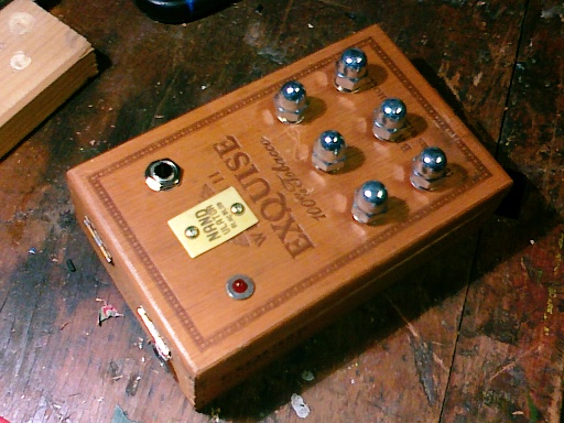
 Exquisite Edition!


