Sorry if this was asked before- but I couldn't find the information. Is it possible to run this VCO from +/-12v? If so, are there any components who's values need to be changed?
Thanks!
Really looking forward to building a couple of these!
no so good, however, there is good news for you:
the project and the PCBs are well tested and build many times, so they are fine. something you can rely on.
so there must be at least one error on your side which you can troubleshoot and solve...
so i recommend troubleshooting as usual.
anyways, from what i understand reading your post, you have some issues with the waveshaper, and some with the core PCB.
i would recommend to completely remove the waveshaper board at first, and get the core board running. if the core board is fine, then add the waveshaper again to see what's the matter with it. _________________
cheers,
matthias
____________
Big Boss at fonitronik
Tech Buddy at Random*Source
1.Turning coarse or fine pots causes pitch to change... except that it is slewed.
5. Triangle out is intermittent
so this is core related. as i said above, remove the waveshaper COMPLTETELY and then check again.
Quote:
2. PWM Init pot is extremely sensitive, you can only hear a pulse output if the PWM init is exactly center.
3. Multimeter shows Pin 1 and Pin 2 of PWM Attn (PCB) connected to ground. The actual pot seems fine.
4. I get no sine output.
re 2 & 4: take a look at the schematic and how the pulse and PWM is done. you have a comparator IC4C that is fed with the sine. so as long as you don't have a sine ouput, you will not get a proper pulse...
re 3: if you removed the pot, removed the PCB completely from the system and still measure GND on pin 2 of the PCB header then there must be a short/solder bridge kind of thing... this pot is nothing but a voltage divider. _________________
cheers,
matthias
____________
Big Boss at fonitronik
Tech Buddy at Random*Source
Joined: Jun 24, 2008 Posts: 152 Location: Mesa, AZ
Audio files: 3
G2 patch files: 6
Posted: Mon Sep 03, 2012 10:15 am Post subject:
I removed the waveshaper. I have a patch cable going into my computer so I can hear what's coming out.
-Ground hum is coming from +/-15v power pins and ground pins.
-Ground hum is coming from ground pads (pad1) and signal pads (pad2) of the pcb (saw and tri pads)
-No waveshape or ground hum is present when cable is inserted into jack.
-I have all jack/signal wires going to pad2 of the PCB
-Check my LM394 connection.
Edit: NOTE I do have a second fully populated X-4046 that I could attempt to wire... or test?? Not sure what tests I'd do. Last edited by elanhickler on Mon Sep 03, 2012 11:22 am; edited 1 time in total
re ground hum:
1. re-check all your grounding/wiring.
2. connection to computer correct?
3. is your PSU clean?
4. what resistance do you measure across +V and GND, resp. GND and -V?
re LM394:
what transistors are you using? is the pin out correct? same as LM394? _________________
cheers,
matthias
____________
Big Boss at fonitronik
Tech Buddy at Random*Source
Joined: Jun 24, 2008 Posts: 152 Location: Mesa, AZ
Audio files: 3
G2 patch files: 6
Posted: Mon Sep 03, 2012 3:20 pm Post subject:
Resistance across gnd/v+ and gnd/v-
Power on: Seems to be infinite resistance???
Power off: Resistance slowly falls to 0 and then goes back up to 2.2K for v+ and 1.45K for v-
Power on: No audible waveform
Power off: A high pitched waveform appears and quickly falls to 0hz at which point a waveform is no longer heard. Both saw and tri outputs exhibit this behavior and the waveshape seems to be correct for the brief moment I get the waveform during power down.
if you used 2N3904 transistors, then it looks like you have an error in the current mirror (Q1/Q2), according to your picture.
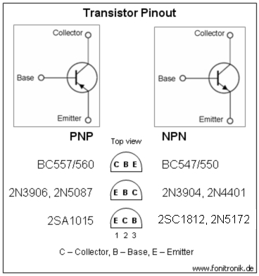
take a look at the 2N3904 pinout here:
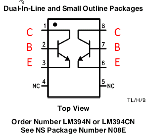
and then take a look at the LM394 datasheet (edited by me):
if you wanted to use 2N3904 the 2nd transistor (pins 5, 6, 7 of the LM394 footprint) would have to be flipped. according to your picture the 2nd transistor is rotated... _________________
cheers,
matthias
____________
Big Boss at fonitronik
Tech Buddy at Random*Source
Joined: Jun 24, 2008 Posts: 152 Location: Mesa, AZ
Audio files: 3
G2 patch files: 6
Posted: Tue Sep 04, 2012 8:31 am Post subject:
fonik wrote:
if you wanted to use 2N3904 the 2nd transistor (pins 5, 6, 7 of the LM394 footprint) would have to be flipped. according to your picture the 2nd transistor is rotated...
Joined: Mar 20, 2012 Posts: 2179 Location: Chicago
Audio files: 16
Posted: Tue Sep 04, 2012 10:11 am Post subject:
Yah, I'd say likely a typo. The bottom line is if you're using 2 NPNs of any sort, they both have to face the same way, they can't face one one way and one the other. Collector will always be the same pin on both, and if you reverse one to make them face each other, you're connecting collector to emitter and emitter to collector.
Hi all ,
Is your faults occuring when the pcbs are stacked on the pillars ??.
It may be several shorts to ground, if it is causing shorts , just use thin nylon washers to isolate.
Joined: Jun 24, 2008 Posts: 152 Location: Mesa, AZ
Audio files: 3
G2 patch files: 6
Posted: Tue Sep 04, 2012 10:05 pm Post subject:
I think I got it working. I switched the transistors legs for "6,7,8" And the saw is supposed to be twice the frequency, right?
The waveshapes seem a little unclean to my ears. That's fine, but just want to make sure my build is as correct as possible. Can someone verify my waveshapes are as they should be? See attached wav file.
Edit: BTW, people describe the hardsync on this as VERY HARD and AWESOME... but I would describe it as very clean, that *is* awesome.
I think I got it working. I switched the transistors legs for "6,7,8" And the saw is supposed to be twice the frequency, right?
yay! that's it!
Quote:
The waveshapes seem a little unclean to my ears. That's fine, but just want to make sure my build is as correct as possible. Can someone verify my waveshapes are as they should be? See attached wav file.
the triangle is a composite of different ramp waveforms. you need the trimmers to set it up properly. and even with an optimum of calibration there will always be a small spike at the turning points of the triangle. some might call it a bug, i would call it a feature, since it adds to the flavour and personality of this VCO (it's always these imperfections that make it special, isn't it?).
the triangle gets shaped to a sine, and again, even with an optimum of calibration you won't get the perfect sine, it will have this little spike, too.
do you have a scope? this would be very helpful for calibration (connect the wave shapes, set the offsets). _________________
cheers,
matthias
____________
Big Boss at fonitronik
Tech Buddy at Random*Source
Joined: Jun 24, 2008 Posts: 152 Location: Mesa, AZ
Audio files: 3
G2 patch files: 6
Posted: Wed Sep 05, 2012 10:52 pm Post subject:
OK! Now I'm adding the waveshaper to the circuit and getting strange behaviors.
1. Sine output is 100% saw-shaped
2. Skew output is SAW ONLY and the skew pot simply turns the volume of the saw up or down. No triangle is heard
3. PWM init is extremely sensitive with the square output being inaudible most of the pot turn.
I checked pot values, I checked wiring... im using a header/pins for the saw/tri in/out. Maybe I have a bad connection there. Multimeter ran out of batteries so I need to recharge it before i can test for connection...
Read carefully: To test to see if the connection was bad I used an alligator clip that went from "TRIANGLE pin2" of the core to "SAW/TRI IN pin1 (triangle)" of the waveshaper. Basically, the waveshaper would in theory be receiving two triangle outputs into its one triangle input... both the "TRIANGLE" and "SAW/TRI OUT" from the core....
-Doing this made the sine output a weird shape in which the sine trimmers could affect, but it could not be trimmed to a sine. Before making this connection, the sine trimmers did nothing.
yeah, could you check that my core waveshapes are correctly trimmed before I add the waveshaper to the circuit? (see above wav). thank you!
okay, we should definately check the core's outputs before tackling the waveshaper.
the problem is: if you recorded this wave with your soundcard all DC offset will be removed, since the inputs of your soundcard are AC coupled (unless you modded it or bought a special soundcard for control voltage use).
nevertheless i will download the wavefile and analyze it.
on the waveshaper board you have at least two different issues, i guess:
1. sine wave (effects pulse, too, and might be due to some offset in the triangle).
2. skew pot (which is very plain and simple, so this should be an easy fix). _________________
cheers,
matthias
____________
Big Boss at fonitronik
Tech Buddy at Random*Source
Read carefully: To test to see if the connection was bad I used an alligator clip that went from "TRIANGLE pin2" of the core to "SAW/TRI IN pin1 (triangle)" of the waveshaper. Basically, the waveshaper would in theory be receiving two triangle outputs into its one triangle input... both the "TRIANGLE" and "SAW/TRI OUT" from the core....
if i got it correct then this is a kind of passive mixing, which i would avoid, especially when you want to test something.
i would just use the multimeter and check the continuity on the signal path. the core produces a triangle. so check continuity between:
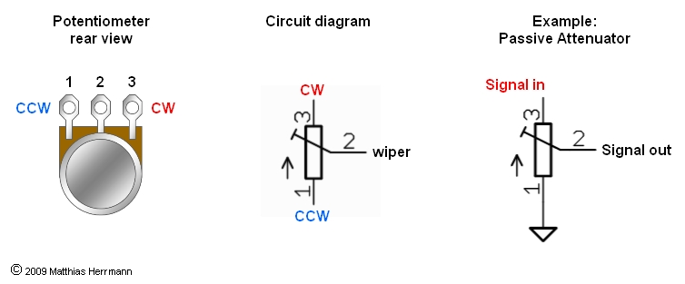
core IC3 pin 8 and waveshaper pot R53 pin 3 (CW) directly on the pot.
here is a picture illustrating where you'll find the CW pin on a potentiometer:
_________________
cheers,
matthias
____________
Big Boss at fonitronik
Tech Buddy at Random*Source
yeah, could you check that my core waveshapes are correctly trimmed before I add the waveshaper to the circuit? (see above wav). thank you!
i looked at the waveorm you recorded using a wave editor. the waves look well connected to me, both the saw and the triangle, however, it is not possible to identify DC offset in a wavefile recorded via a soundcard.
nevertheless, when the saw ends in your file, i see a long slope going down to 0V. this could be due to an offset corrected by the AC coupling capacitor at the input of your soundcard. i am not sure. _________________
cheers,
matthias
____________
Big Boss at fonitronik
Tech Buddy at Random*Source
Joined: Jun 24, 2008 Posts: 152 Location: Mesa, AZ
Audio files: 3
G2 patch files: 6
Posted: Thu Sep 06, 2012 12:41 pm Post subject:
fonik wrote:
i see a long slope going down to 0V. this could be due to an offset corrected by the AC coupling capacitor at the input of your soundcard. i am not sure.
Fonik, smart call! HEY GUESS WHAT? VCO IS WORKING 100%!!!!! Sine is very unexpectedly clean!
I trimmed the saw and tri offset by repeatedly plugging and unplugging the waveform and watched how my audio interface removed the DC offset. So, if I plug in the waveform and it slopes up or down before settling, that means I adjust the trimmers until this doesn't happen. I'll have to re-trim when I have a method of actually seeing the DC offset.
So far:
-A transistor was reversed *FIXED*
-There was no connection from tri out of core to tri in of waveshaper *FIXED*
ONE little problem is left. My pulse init is still too sensitive. What parts should I check for correctness?
before talking about the pulse, how does the sine wave look? maybe you could send me a wavefile from the sine output (m at fonitronik dot com)? _________________
cheers,
matthias
____________
Big Boss at fonitronik
Tech Buddy at Random*Source
i took a look at the wave file you sent me via emal, and indeed the sine wave seems to be a little bit weak compared to the other outputs. the shape looks quite fine though. no idea how to solve that by now. so for now re-check all components values again...
if you could live with that, and just want to get a better pulse width control, then let me ask the following: is it just the manual control that is unsatisfying, or do you find the CV control (PWM) too sensitive, too? _________________
cheers,
matthias
____________
Big Boss at fonitronik
Tech Buddy at Random*Source
You cannot post new topics in this forum You cannot reply to topics in this forum You cannot edit your posts in this forum You cannot delete your posts in this forum You cannot vote in polls in this forum You cannot attach files in this forum You can download files in this forum


 Forum index » DIY Hardware and Software » fonik's place


 FAQ
FAQ Calendar
 Search
 Memberlist
 Usergroups
 Register
 Profile
 Log in to check your private messages
 Log in
 Chat Room